
Modeling Pre-Engineered Buildings (PEB) & Purlin/Girt Layouts with Millimeter Precision
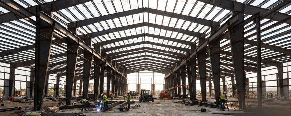
- PEB/PEMB structures use built-up tapered columns and rafters with varying web depth and flange thickness that need precise 3D modeling.
- Cold-formed Z and C purlin/girt systems require detailing of lap splices, eave struts, sag rods and flange braces.
- Standardizing connection plates and hole patterns across the frame speeds up both shop fabrication and field erection.
Pre-Engineered Buildings (PEB/PEMB) utilize non-standard built-up tapered members, cold-formed Z/C purlins, and complex bracing networks that demand meticulous 3D modeling.
Tapered Member Modeling
Accurately construct built-up plate columns and rafters with varying web depths and flange thicknesses.
Cold-Formed Secondary Framing
Detail Z and C purlin/girt systems, including lap splices, eave struts, sag rods, and flange braces.
Optimization & Standardization
Ensure connection plates, cleat angles, and hole patterns are standardized across the frame to simplify shop fabrication and speed up field erection.
Bracing and Bridging Layouts
Purlin and girt bracing is where a lot of PEB modeling time disappears if it's treated as an afterthought. Rod bracing between purlin lines, flange bracing at the compression flange to prevent lateral-torsional buckling, and bridging at specified intervals along the purlin run all need to be modeled as real 3D members with their own connection details, not left as a note on the drawing for the erector to figure out — a common source of field RFIs on PEB jobs is bracing shown schematically on the roof plan but never actually detailed with a connection.
Coordinating the PEB Model with the Building Manufacturer's Software
Most pre-engineered building manufacturers generate their own frame design and initial member list in proprietary software before the model ever reaches Tekla, which means the detailing team's first job is reconciling that manufacturer output against the detailing model rather than starting from a blank file. Member sizes, base reactions, and bay spacing need to match exactly between the two systems; a rounding difference in a purlin spacing dimension between the manufacturer's output and the Tekla model is a small discrepancy that becomes a real fit-up problem once girts and wall panels are added on top of it.
Handling Openings and Penetrations in the Envelope Framing
Wall and roof openings — doors, louvers, skylights, roof-top unit curbs — interrupt the standard girt and purlin spacing and require their own framing around the opening, which has to be modeled and detailed as carefully as the primary structure even though it's a smaller quantity of steel. A common source of field problems on PEB jobs is an opening shown on the architectural plan but never reflected in the secondary framing model, leaving the erection crew to improvise trimmer and header framing on site without a drawing to work from. Cross-checking every architectural opening against the secondary framing model before the drawing set is released catches this gap while it's still a modeling fix rather than a field improvisation.
Documenting Assumptions for the Erection Crew
Because PEB secondary framing relies on a large number of repeated, similar-looking members, an erection crew benefits enormously from a drawing set that documents the underlying pattern — standard purlin spacing, where and why that spacing changes near an opening or a bay end, the bracing pattern's logic — rather than only a flat list of individual piece locations. A crew that understands the pattern can catch their own errors in the field (a purlin that doesn't fit the expected spacing signals something worth double-checking); a crew handed only a piece list has no way to sanity-check what they're installing against what should be there.
Because PEB projects are often on aggressive schedules, it's also worth building in a specific checkpoint for reconciling the manufacturer's latest frame revision against the detailing model before girts and purlins are finalized — PEB manufacturers do sometimes revise frame design after the initial package is issued, and a secondary framing model built against an earlier frame revision can end up dimensionally correct for a building that no longer matches what's actually being fabricated.
Frequently asked questions