
Applying AISC & AWS Codes in Steel Connection Detailing: Avoiding Engineer Rejections
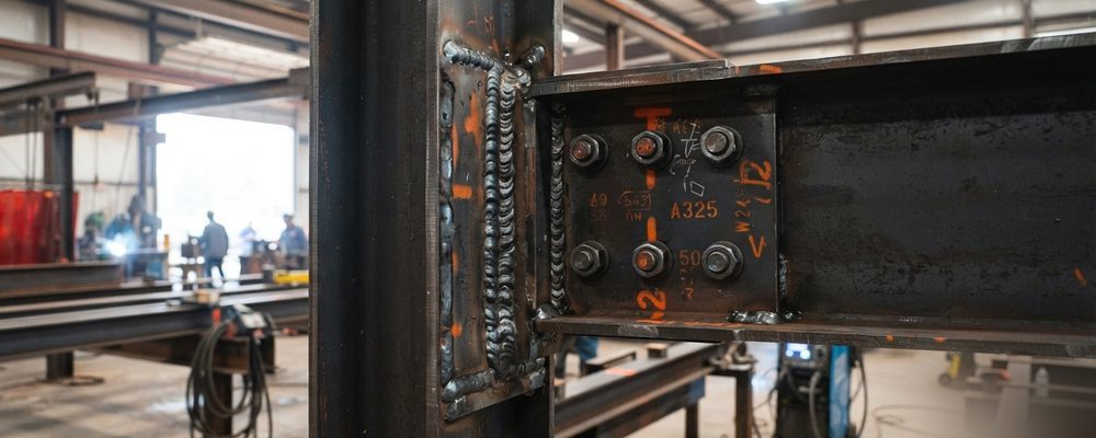
- Most engineer rejections trace back to bolt edge distance, hole spacing or wrench clearance errors against AISC minimums.
- AWS weld symbol mistakes — wrong fillet/groove size, bevel angle or CJP vs PJP designation — are the second most common rejection cause.
- Stiffener and doubler plate details must match the engineer's calculations exactly while still leaving room for shop fabrication access.
Submittals rejected by structural engineers stall project progress and erode client trust. Detailers must apply American Institute of Steel Construction (AISC) and AWS design rules directly within connection models.
Bolt Spacing & Edge Distances
Adhere to AISC minimum bolt edge distance rules, hole spacing specifications, and wrench clearance requirements.
AWS Weld Symbol Compliance
Correctly denote fillet welds, bevel preparation angles, groove weld sizes, and differentiate CJP vs. PJP welds.
Stiffener & Doubler Plate Details
Detail column web stiffeners, doubler plates, and moment connection details to match structural engineering calculations without compromising fabrication access.
Common Rejection Reasons and How to Avoid Them
Engineers reject connection details for a small, repeatable set of reasons, and most of them are catchable before the drawing ever leaves the shop. Missing weld-access holes at moment connections, a fillet weld size shown without the matching effective throat check, and slip-critical bolted joints detailed without calling out the faying-surface class are the three that show up most often in review comments. None of these require redesign — they require a detailer who checks the connection type against a short mental list before the drawing is released.
Camber and sweep notes are another frequent miss. A beam detailed as straight when the erection drawing calls for induced camber will fit the model perfectly and still fail in the field, because the mill camber, fabrication camber, and any field-induced camber all need to be reconciled on the same drawing rather than assumed to match.
Coordinating Connection Design with the Engineer of Record
On projects where connections are delegated to the fabricator (a common arrangement under AISC's delegated-design provisions), the detailer's shop drawing is often the first place the actual connection geometry gets defined, not just documented. That puts the detailing team in the RFI loop earlier than they might expect: any deviation from the contract drawings — a different bolt pattern, a added stiffener, a change in weld type — needs a submittal back to the EOR with enough detail (bolt grade, weld symbols, plate thickness) that the engineer can check capacity without asking a follow-up question. Building that submittal package as a standard step in the workflow, rather than an afterthought once the EOR pushes back, is what keeps a shop drawing set moving through review in one pass instead of three.
Building a Connection Checklist Into the Release Process
Most of the rejection reasons above share a common fix: a short, standing checklist the detailer runs through before any connection drawing is released, rather than relying on memory or catching problems only when the EOR sends them back. A useful checklist is specific rather than generic — "weld access hole shown for all moment connections," "faying surface class noted for every slip-critical joint," "bolt grade matches the connection's required slip or bearing capacity" — and gets updated every time a new rejection reason shows up on a real project, so the list reflects the mistakes this team actually makes rather than a generic industry list.
Over several projects, that checklist becomes one of the most valuable documents a detailing team owns, because it encodes lessons that would otherwise live only in one senior detailer's head and get lost when that person moves to a different project.
Keeping Up with Code Edition Changes
AISC and AWS codes are revised on a regular cycle, and a detail that was compliant under one edition can fail review under the next if a project spans an edition change or if a detailer is working from an outdated reference without realizing it. Confirming which code edition governs a specific project — stated in the contract documents, not assumed from habit — before detailing begins, and flagging it clearly in project standards, avoids the awkward situation of a full drawing set needing rework because it was detailed against the wrong edition's provisions.
Frequently asked questions