
3D BIM Modeling vs. Traditional 2D CAD Detailing: Why Global Fabricators Are Dropping 2D
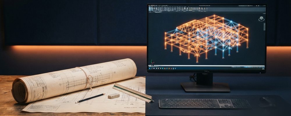
- 3D BIM (Tekla) auto-updates shop drawings, section views and material schedules when a member changes; 2D CAD requires manual redlines across every file.
- 3D BIM exports NC/DSTV data straight to CNC machines and generates live BOM reports; 2D CAD offers neither.
- Clash detection is automated in 3D BIM during modeling, while 2D CAD relies on manual overlay checks that miss spatial conflicts.
Traditional 2D CAD drafting is increasingly inadequate for modern steel construction due to its reliance on manual drawing updates, elevated risk of human error, and inability to produce automated CNC machine data. Dynamic Parametric Modeling vs. Static Lines: In 3D BIM (Tekla Structures), altering a member's size or position automatically updates all associated shop drawings, section views, and material schedules. 2D CAD requires manual revisions across multiple individual drawing files.
Automated Data Integration
3D BIM exports NC/DSTV data for direct machine cutting, generates real-time BOM reports, and integrates with shop-floor production management software.
Clash Detection Capabilities
3D BIM identifies spatial conflicts digitally during modeling, whereas 2D CAD relies on manual drawing overlays that frequently miss geometric clashes.
| Capability | Traditional 2D CAD | 3D BIM (Tekla Structures) |
|---|---|---|
| Drawing Revisions | Manual update per file | Automated global updates |
| CNC Machine Support | None / manual re-entry | Direct NC / DSTV export |
| Clash Detection | Manual overlay | Automated 3D detection |
| BOM Generation | Manual counting | Automated & real-time |
Moving a Team from 2D to 3D
The switch rarely happens overnight. Most fabrication shops run a hybrid period where senior detailers model in Tekla while junior staff still mark up 2D redlines, and that overlap is where mistakes creep in if the two data sets aren't reconciled on a fixed schedule. A realistic rollout treats the first project as a pilot: pick a mid-complexity job, model it fully in 3D, and measure the revision cycle time against a comparable job that was still drafted in 2D.
The steepest part of the learning curve isn't the software interface — it's building the discipline of modeling every connection as a true 3D object instead of a symbol. Detailers coming from CAD often under-model connections early on because a 2D symbol was "good enough," which then produces false clashes or missing bolts later. Investing a few weeks in a shared connection-detail library before full production starts pays that back many times over across the life of the model.
What 2D CAD still gets right: for a one-off miscellaneous piece, a single repair detail, or a quick markup sent to the shop floor same-day, opening a CAD file and drawing three lines can be faster than touching a full building model. Most detailing teams that have moved to 3D BIM keep a lightweight 2D tool on hand for exactly these small, disposable sketches — the goal isn't to eliminate 2D entirely, it's to stop using it for anything that will be revised more than once.
Model Element Standards That Make the Switch Stick
Teams that struggle after moving to 3D BIM usually aren't struggling with the software — they're struggling because they never agreed on a shared modeling standard before production started. Two detailers on the same job modeling the same connection type with different levels of detail, different naming conventions for custom components, or different rules for when a bolt group becomes its own object versus part of a larger assembly produces a model that's internally inconsistent even though every individual part is technically correct.
A short written standard — naming conventions, minimum level of detail per connection type, which custom component library to draw from — agreed before the first member is modeled saves far more rework than any amount of individual detailer skill can compensate for after the fact. This matters more, not less, as a team scales from one detailer to several working the same model in parallel.
Frequently asked questions