
Mastering Complex Structural Steel Geometry: Resolving Site Clashes Before Fabrication
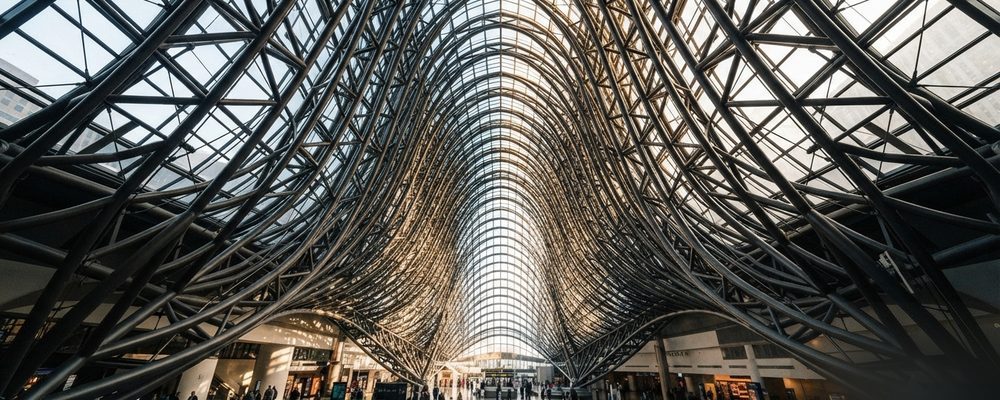
- Spatial trusses, curved roofs and skewed connections need parametric 3D modeling — 2D CAD alone can't capture the geometry accurately.
- BIM clash detection surfaces MEP and concrete conflicts early, before they become field modification costs.
- Complex geometry still needs to extract cleanly into unfolded plate layouts, DSTV cutting files and marking plans keyed to unique piece marks.
Complex geometric structures—such as spatial trusses, curved roofs, and skewed connections—cannot be detailed accurately using 2D CAD alone.
Parametric 3D Modeling
Tekla Structures models complex joints, plate cuts, and bolt groups with millimeter precision.
BIM Clash Detection
Digital coordination reveals physical overlaps with MEP and concrete structures early, preventing field modification costs.
Extraction of Fabrication Data
Direct extraction of unfolded plate layouts, DSTV cutting files, and Erection Marking Plans keyed to unique piece marks.
Handling Curved and Twisted Members
Curved and twisted steel — barrel-vault roof members, helical stair stringers, warped canopy framing — forces a choice between modeling the true curve or approximating it as a series of straight segments (a faceted or chord approximation). The right choice depends on fabrication method: if the piece will be rolled or formed to a continuous curve in the shop, model the true curve so the model matches the physical part; if it will be fabricated as short straight segments welded at angle breaks, model it that way from the start so the shop drawing shows the actual break points rather than a smooth curve the shop then has to reverse-engineer into segments.
Camber and sweep tolerances compound on curved geometry in ways they don't on straight members, because a small angular error at each segment break accumulates over the length of the curve. Building in a running dimension check — comparing the modeled endpoint of a curved assembly against the design geometry after every segment is added — catches drift before it becomes a field fit-up problem.
Coordinating Geometry Changes with the Engineer of Record
When resolving a clash requires moving a member's geometry rather than just its position — changing a curve radius, splitting a member differently, or adjusting a connection to clear an obstruction — that change usually needs to go back to the EOR for sign-off, since it can affect the member's structural behavior even when the clash itself is a coordination issue rather than a design one. Flagging geometry-affecting resolutions separately from simple position clashes in the coordination log keeps those approvals from getting lost among the much larger number of routine clashes.
Validating Complex Geometry Before It Reaches the Shop
Complex, non-orthogonal geometry benefits from a validation step that simpler rectilinear framing doesn't strictly need: generating a physical or high-fidelity digital mockup of at least one representative connection before the full package is released, to confirm that a geometrically valid 3D model actually translates into a buildable, weldable, bolt-up-able connection in the real world. A model can be dimensionally perfect and still describe a connection that no welder can physically reach with a torch or a worker can physically reach with a wrench — and that gap only shows up in a mockup, not in a clash report.
Communicating Complex Geometry to the Fabrication Shop
A shop drawing for complex geometry has to work harder than a drawing for orthogonal framing, because the shop floor can't rely on intuition to sanity-check a curved or twisted member the way they might for a standard beam. Adding reference dimensions at multiple points along a curve, calling out the specific fabrication method assumed (rolled, formed, or segmented), and including an isometric or 3D view alongside the standard orthographic views all help a fabricator catch a modeling error before cutting steel, rather than discovering a geometry problem only once the piece is on the shop floor and doesn't match expectations.
Frequently asked questions